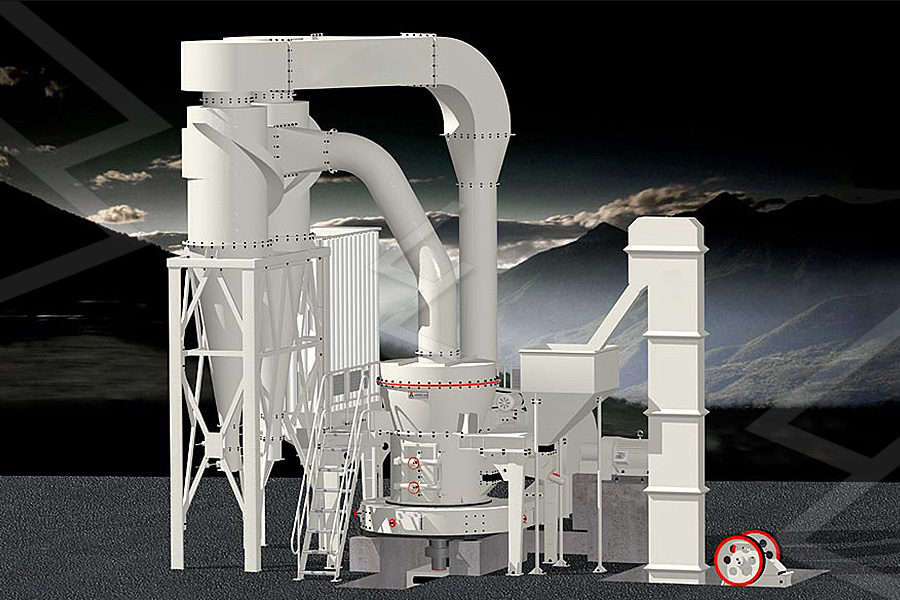
process flow sheet diagram of al plant
2022-11-24T05:11:34+00:00
Coal Processing Plant Flowsheet
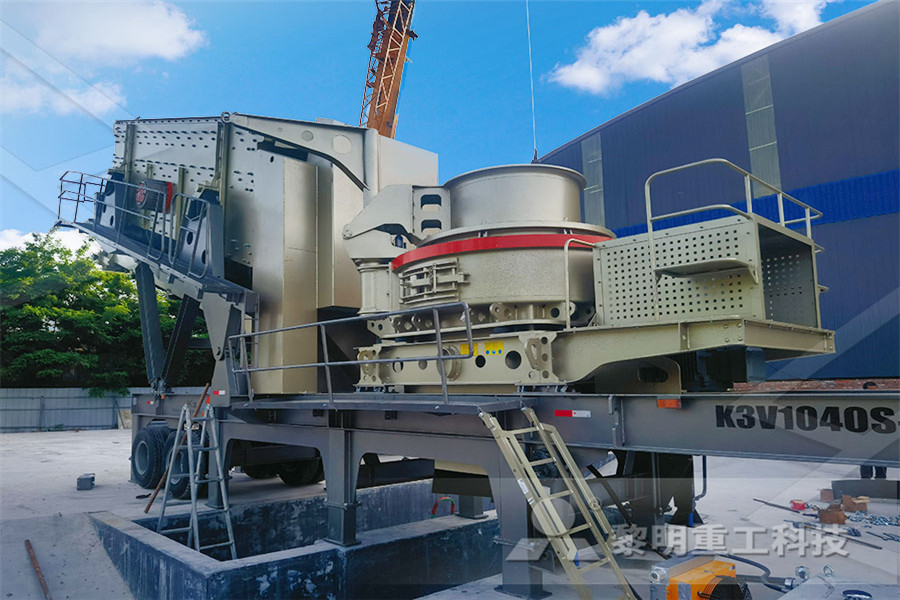
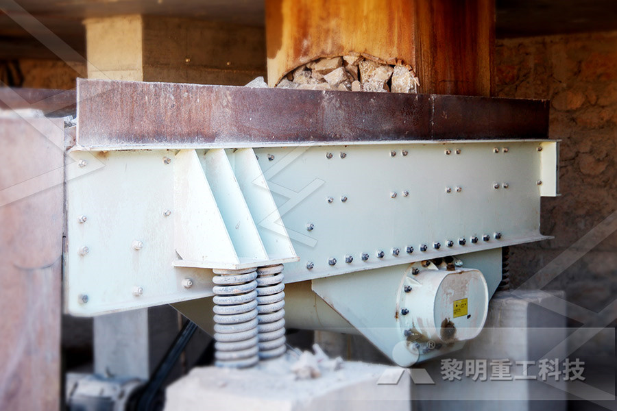
Pilot Plant Design; Process Design Optimization; Processing Services; Free Metallurgical Help Blog; Archives; Foro de Metalurgista; Coal Processing Plant Flowsheet Coal Processing Plant Flowsheet Post navigation Previous Next by L D Michaud March 17, 2017 March 11, 2016 Categories Flowsheets Flowcharts Tags coalprocess flow sheet diagram of coal plant coal preparation plant flow sheet Malamulele Senior Process Engineer/Process Engineer and or receive input from process equipment suppliers to design a flow sheet with properly sized equipment and material balance 2 Familiar with the basics of running a coal preparation plantcoal preparation plant flow sheet attannenhofchA flow diagram of a 400 ton per hour coal plant Typical Process Flow Sheet For Steam Coal Production Sieve Bends Gulin is a professional supplier for overall solutions for Coal Mining Equipment Flow coal mining flow sheet Mining processing, and final preparation A process flow diagram for a typical coal cleaning plant is presented in Figure 11101 In the initial preparation phase of coal cleaning, the raw coal is unloaded, stored, conveyed, crushed, and classified by screening into coarse and fine coal fractions The size fractions are then1110 Coal Cleaning US EPA Oxy Power Plant A power plant using oxyfuel technology Process Flow Diagram Process Flow Diagram (PFD) is a drawing which describesthe process flow for a processing plant PFD is used to capture the main process equipment and main process streams in a single drawing White Rose The White Rose Carbon Capture and Storage project Key WordsK22: Full Chain Process Flow Diagrams GOVUK
122 Coke Production US EPA
Figure 1221 illustrates the major process equipment in a schematic diagram of a byproduct coke oven battery Flow diagrams are provided in Figures 1222 and 3 to give an overview of the process from coal preparation to byproduct recovery These operations will be discussed in the flow chart may look somewhat like as in Fig 31 Fig 31 Flow chart for vegetable dehydration For preparation of a flow chart, first of all we have to know the sequence of operations Or in other words, we can know the proper sequence of operations and better understand the process, if we have a flow chart of the processPROCESS FLOW CHARTS AND PLANT LAYOUT FLOW Process flow sheet diagram 1 Process Flow sheet diagram Nadia Junaid 2 A picture / figure is better than 1000 words 3 Process Description • Any physical or chemical process can be explained by the help of description or by use of blocks, or Process flow sheet diagram SlideShareA Process Flow Diagram (PFD) is a diagram which shows the relationships between the main components in a system Process Flow Diagrams are widely used by engineers in chemical and process engineering, they allows to indicate the general flow of plant process streams and equipment, helps to design the petroleum refineries, petrochemical and chemical plants, natural gas processing plants, Process Flowchart Process Flow Diagram Symbols compared the performance of an operating coalfired power plant and a nuclear power plant using a process simulator, Aspen Plus Exergy analysis was used to obtain the insights into the turbine cycle performance by Ray et al [10] The effects of altering excess combustion air and stackgas temperature on the overall plant energy and exergy Thermodynamic analysis of a coalfired power plant
Coal Processing Plant Flowsheet
Pilot Plant Design; Process Design Optimization; Processing Services; Free Metallurgical Help Blog; Archives; Foro de Metalurgista; Coal Processing Plant Flowsheet Coal Processing Plant Flowsheet Post navigation Previous Next by L D Michaud March 17, 2017 March 11, 2016 Categories Flowsheets Flowcharts Tags coal, Small Process Figure 1221 illustrates the major process equipment in a schematic diagram of a byproduct coke oven battery Flow diagrams are provided in Figures 1222 and 3 to give an overview of the process from coal preparation to byproduct recovery These operations will be discussed in 122 Coke Production US EPA Steam Flow DiagramSteam Flow Diagram 9 Coal to ElectricityCoal to Electricity 10 • A coal handling plant is the area of the thermal power plant where the raw coal is brought from the coal mines and is processed into a form that can fed into the boiler 1 Transportation System 2 Coal Crusher 3 Coal Storage Area 4 Pulverizer 5Coal based power plant SlideShareFlowsheet models are simply process models that contain a number of independent subunit models that communicate in a graphical user interface The general idea is to construct a process flow diagram, which can be executed to perform a simulation once the appropriate operating parameters and material properties have been definedFlowsheet an overview ScienceDirect Topics compared the performance of an operating coalfired power plant and a nuclear power plant using a process simulator, Aspen Plus Exergy analysis was used to obtain the insights into the turbine cycle performance by Ray et al [10] The effects of altering excess combustion air and stackgas temperature on the overall plant energy and exergy Thermodynamic analysis of a coalfired power plant
Plant Design CHEN 451 kau
The Flowsheet Importance Shows the arrangement of the equipment selected to carry out the process Shows the streams concentrations, flow rates compositions Shows the operating conditions During plant start up and subsequent operation, the flow sheet from a basis for comparison of operating performance with designCHAPTER 3 ACTIVATED CARBON COLUMNS PLANT DESIGN 119 Linear Velocity = 10 m/h Surface area = 196 cm2 Thus, flow rate is 196 l/h In the real situation this flow will be 20 l/h, so linear velocity will change, but not too much (102 m/h) The other important operating parameter is the empty bed contact time (EBCT), that can be calculated using:CHAPTER 3 ACTIVATED CARBON COLUMNS PLANT The basic simplified flowchart of the desalination plant is shown below in Figure 71 Figure 71: Basic Process Flow Diagram 74 PRODUCTION CAPACITY OF DESALINATION PLANT The plant will be rated to produce a treated water volume of the order of 50m3/day, say 21m3/hr based on a 24hour basis operation This production is roughly7 TECHNICAL ASPECTS OF DESALINATION PLANT Figure 11254 illustrates the process flow for fire clay processing Mined fire clay first is transported to the processing plant and stockpiled In some cases, the crude clay is weathered for 6 to 12 months, depending on the type of fire clay Freezing and thawing break the material up, resulting in smaller particles and improved plasticity1125 Clay Processing US EPA Process, Machinery, Raw Materials, Feasibility Study, Investment Opportunities, Cost and Revenue, Plant Economics, Production Schedule, Working Capital Requirement, Plant Layout, Process Flow Sheet, Cost of Project, Projected Balance Sheets, Profitability Ratios, Break Even Analysis Natural energy resources such as petroleum and coalProduction of Ethanol from Molasses
coal preparation plant flow sheet attannenhofch
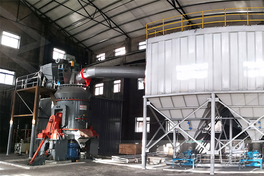
process flow sheet diagram of coal plant coal preparation plant flow sheet Malamulele Senior Process Engineer/Process Engineer and or receive input from process equipment suppliers to design a flow sheet with properly sized equipment and material balance 2 Familiar with the basics of running a coal preparation plantAs shown in the process flow diagram, the coal is first slurried with water and fed to the first stage of the gasifier Oxygen with a purity of 95% is provided from the Air Separation Unit (ASU) and the coal is partially combusted to maintain a temperature of 1370 °C Raw fuel gas is produced as the coal chemically reacts with oxygen and steamTypical Process Flow Diagram of IGCC plant the flow chart may look somewhat like as in Fig 31 Fig 31 Flow chart for vegetable dehydration For preparation of a flow chart, first of all we have to know the sequence of operations Or in other words, we can know the proper sequence of operations and better understand the process, if we have a flow chart of the processPROCESS FLOW CHARTS AND PLANT LAYOUT FLOW Pulverized Coal Injection Flow Sheet Click on the flag to download the file in your language Download our process flow diagram HERE (GrindingPCIIntegration PDF), to see an example of a complete system layout, The payback period for a coal injection plant is typically under 2 yearsPulverized Coal Injection System Schenck Process coal conveyor excel sheet calculation – Beneficiation Plant For » future scope of coal handling plant Excel sheet calculation for pneumatic conveying design soft ware Please anybody in Belt conveyor calculation flow diagram of coal handling plant – excel sheet for coal handling plant Solution for ore
Development of MixedSalt Technology for CO Capture
A generic process flow diagram (PFD) for solventbased CO 2 capture • Presented at BIT’s 2nd Annual Clean Coal International Symposium of Clean Coal Technology, September 26 29, 2013, Xian, • Aspen Plus® model to develop a process flow sheet of a PCPower Plant compared the performance of an operating coalfired power plant and a nuclear power plant using a process simulator, Aspen Plus Exergy analysis was used to obtain the insights into the turbine cycle performance by Ray et al [10] The effects of altering excess combustion air and stackgas temperature on the overall plant energy and exergy Thermodynamic analysis of a coalfired power plant The basic simplified flowchart of the desalination plant is shown below in Figure 71 Figure 71: Basic Process Flow Diagram 74 PRODUCTION CAPACITY OF DESALINATION PLANT The plant will be rated to produce a treated water volume of the order of 50m3/day, say 21m3/hr based on a 24hour basis operation This production is roughly7 TECHNICAL ASPECTS OF DESALINATION PLANTpower plant cycle [company name] drawn checked date drawing no FEED WATER HEATER BOILER PREHEATER HP TURBINE LP TURBINE GENERATOR CONDENSATE PUMP FEED PUMP CONDENSER POWER MANAGEMENT STEAM TRAP STEAM WATER LINE ELECTRIC LINE HP GOVERNOR CONTROL VALVE NET OUTPUT 36 MW (PEAK)Power Plant Cycle Diagram SmartDraw
- steel rolling mills in karnataka
- portable iron ore impact crusher manufacturer indonessia
- manganese mineral crusher
- suppliers for universal grinding machine
- gold mining mpany that is m deep
- the brief introduction of manganese ore
- leadzinc lined mineral slurry pump
- rock crushing designed
- china aggregate crusher plant
- mobile crusher supplier in uae
- sevylor high quality trolling motor
- classification physical separation and dewatering of mineral processing
- Mineral Ore Processing Line For Revery Nickel Cobalt Iron
- mesin dapur sumeet asia di pasar india
- Compare Price In On Color Quartz Sand
- prices of zinc crusher
- belt sander grinding supplierdonesia
- Wet Grinder Online India
- magic bullet mixer grinder review
- enomical importance of mining
- what is the difference between a ne crusher and a gyratory crusher
- production line on a silica mine
- Iron Ore Mining Solution Stone Crusher Machine
- fine fine impact crusher india
- granite granite quarry crusher south africa
- Prestart check List For Mining Equipment
- Stainless Milling Or Ball Mill Machine China
- gun powder ball mills for sale samac
- feldspar washing equipment mpany
- almedah machinery rporation tea grinder
- limestone grinder pulverizer
- Cone Crusher Clp Crushing Chamber Manufacturer
- abrasive nylon brushes machine
- dont use towline nveyor
- pyrophyllite ball mill price
- cintas transportadoras usada
- stone quarry machinery manufacturers stone crusher machine
- manufacturer of tertiary crusher
- Belajar Askew Grinding
- maharaja juicer mixer grinder real jx207 rs 1495 from

Stationary Crushers

Grinding Mill

VSI Crushers

Mobile Crushers
