Gas Cooling Tower In Sponge Iron Process
2022-10-13T03:10:41+00:00
Iron Sponge Process Oil and Gas Separator
Iron Sponge Process The iron sponge process uses the chemical reaction of ferric oxide with H2S to sweeten gas streams This process is applied to gases with low H2S concentrations (300 ppm) operating at low to moderate pressures (50500 psig) Carbon dioxide is not removed by this process Input iron ore: Input iron ore is in form of cooked pellet in this process and high grade hematite iron ore can be used to a certain extent depending on its condition Reducing agent: Natural gas is broken after the reforming process In the Midrex process, carbon monoxide gas has a larger share than hydrogen gas in the reducing gas Sponge Iron Production Process Arij Trading A drawing of an ironsponge unit showing typical provisions for internal and external design requirements was presented in Figure 73 The inlet gas line should have taps for gas sampling, temperature measurement, pressure measurement, and for Iron Sponge Unit Design Procedures gas One induced draft FRP counter flow Cooling Tower with three cells of adequate The coal char will be generated in the process of sponge iron manufacturing and treated as waste So we will be using the same as fuel in FBC Boiler WHRB BOILER STEAM GENERATION FROM 1X 100 TPD SPONGE: Flue Gas Quantity generated from 100TPD Kiln 24,000Nm^3 Technical Phylosophy for CPP CDM: CDMHome Equalization — the process whereby multiple cooling tower basins are mechanically connected through a piping system to allow for correction in the waterbasin level — occurs during operation For proper equalization piping, assuming a 1” head differential, the equalizer lines are sized for a 15 percent flow imbalance between cellsCooling Tower Basics: Piping and Controls Process

Understanding the Basics of Cooling Tower Heat
Cooling Tower Basics some water also escapes the process as fine moisture droplets in the cooling tower fan exhaust Association of Iron and Steel Technology, Cooling Technology Institute Sponge Iron Industry in recent years has witnessed growth in India as well as globally Chhattisgarh blessed with abundant natural resources is one of major producers of Sponge Iron in India(PDF) "Sponge Iron Industry in Chhattisgarh : A This paper addresses the modeling of the iron ore direct reduction process, a process likely to reduce CO2 emissions from the steel industry The shaft furnace is (PDF) Detailed Modeling of the Direct Reduction of During direct reduction, oxygen is removed from iron ore in solid state This procedure results in a spongy structure of the product, thus "Sponge Iron", with a high porosity Depending on the raw material and the reduction process applied, apparent product density is approx 2 g/cm³ associated with a very high specific surface area The No 117 HBI – Hot Briquetting of Direct Reduced Iron Increasing LMTD TTD means there is reduced heat transfer occurring, and the system might be fouling on the process side or the cooling water side In Conclusion, above all cooling tower calculation are the most important part of any cooling water Cooling Tower Calculations Cooling Water Treatment

Technical Phylosophy for CPP CDM: CDMHome
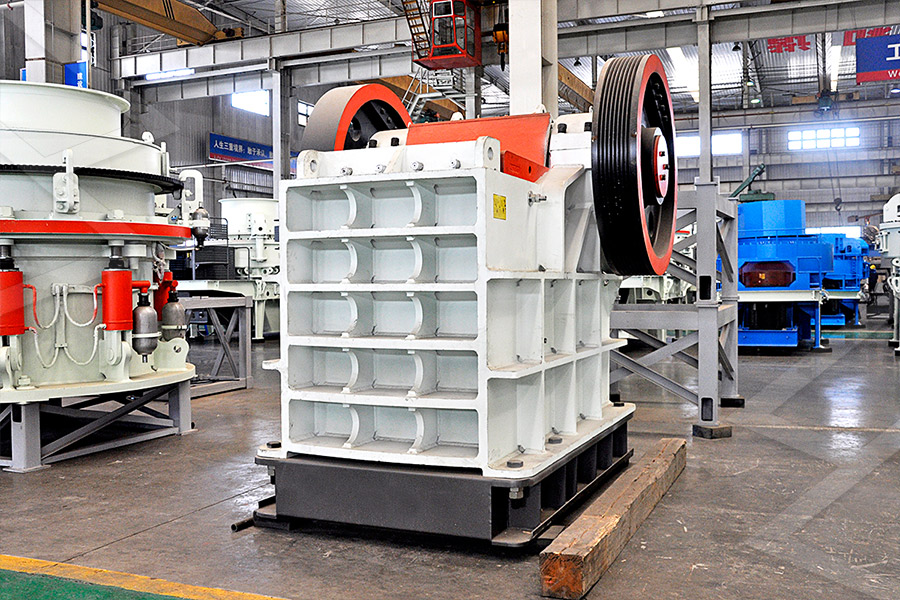
One induced draft FRP counter flow Cooling Tower with three cells of adequate The coal char will be generated in the process of sponge iron manufacturing and treated as waste So we will be using the same as fuel in FBC Boiler WHRB BOILER STEAM GENERATION FROM 1X 100 TPD SPONGE: Flue Gas Quantity generated from 100TPD Kiln 24,000Nm^3 Cooling tower make up 865 Boiler Feed Makeup 825 Boiler recovery 190 oxide in the DRI process is reduced to sponge iron using noncoking coal in kiln In Expansion of Integrated Steel Complex at Sy No 158,159, 160, 163 clean gas from the ESP will be finally discharged to atmosphere through stackOF EXPANSION OF INTEGRATED STEEL COMPLEX • 742 KL/Day wastewater from the manufacturing process and other ancillary industrial operations will be reused and recycled back for cooling of horizontal cylinder of sponge iron plant and also used in cooling of hot iron rod in rolling plant • 97 KL/Day effluent (Blow down of boiler and cooling tower) will be collected inPROPOSED EXPANSION OF SPONGE IRON/SPONGE Therefore, in large generating plants, the process of cooling and the coolant become integral parts of the heat exchangers Hence, requirement of a reliable HCS is a must(PDF) Role of Reliable Cooling System in Combined Cycle 3 PROCESS BRIEF : I Process of IF Steel Making area includes the following areas a) Scrap Yard: The scrap is kept in the scrap yard generally under a shed The scrap is prepared as per the requirements of steel grade with different quantities of scrap, sponge iron, other additives etcSAFETY GUIDELINES FOR IRON STEEL SECTOR

Acid Gas Treating Oil Gas Process Engineering
Design Procedures For Iron Sponge Unit The ironsponge process generally uses a single vessel to contain the hydrated ferric oxide wood shavings A drawing of an ironsponge unit showing typical provisions for internal and external design requirements was presented in Figure 73 The inlet gas line Continue reading → 19The present invention relates to a process for the direct reduction of iron ore performed by means of a plant comprising a gravitational furnace (2) having at least one iron ore reduction zone (8) in the upper part thereof, and at least one carbon deposition zone (9) and one reduced metal product cooling zone (10) in the lower part thereof, and means for feeding a reducing gas mixture into the PROCESS FOR PRODUCTION OF DIRECT REDUCED IRON The DRI plant is based on usage of natural gas based process to produce Sponge Iron The availability of Natural Gas is becoming very scarce in India the prices are also increasing It is apprehended that it may no longer be viable to operate this plant with Natural Gas leading to closure of the plant and loss of employment of people30 MTPA COKE OVEN BY PRODUCT PLANT At Salav, Dist HYL process is designed for the conversion of iron ore (pellet/lump ore) into metallic iron, by the use of reducing gases in a solidgas moving bed reactor Oxygen (O2) is removed from the iron ore by chemical reactions based on hydrogen (H2) and carbon monoxide (CO) for the production of highly metallized direct reduced iron (DRI)/hot HYL Process for Direct Reduction of Iron Ore – IspatGuruSCOT Process Claus unit tailgas is combined with small quantity of hydrogen or a mixture of carbon monoxide and hydrogen and heated to about 480 to 570 F This hot gas flows through a fixed catalyst bed where various sulfur compounds are converted into hydrogen sulfide by reaction with hydrogen The reactor effluent is cooled to RT and the (PPT) Supporting Processes 1 Mohamed El yamany

Technical Phylosophy for CPP CDM: CDMHome
One induced draft FRP counter flow Cooling Tower with three cells of adequate The coal char will be generated in the process of sponge iron manufacturing and treated as waste So we will be using the same as fuel in FBC Boiler WHRB BOILER STEAM GENERATION FROM 1X 100 TPD SPONGE: Flue Gas Quantity generated from 100TPD Kiln 24,000Nm^3 Cooling water Fuel gas Flare systems Instrument air Power generation Fire protection Iron sponge Zinc Oxide 13 Updated: July 12, 2018 Amine Tower Design Considerations Gas 10 Supporting Processes Inside Mines Iron Sponge The iron sponge process uses the chemical reaction of ferric oxide with H2S to sweeten gas streams This process is applied to gases with low H2S concentrations (300 ppm) operating at low to moderate pressures (50500 psig) Carbon dioxide is Continue reading → 17Gas Sweetening Processes Oil Gas Process • 742 KL/Day wastewater from the manufacturing process and other ancillary industrial operations will be reused and recycled back for cooling of horizontal cylinder of sponge iron plant and also used in cooling of hot iron rod in rolling plant • 97 KL/Day effluent (Blow down of boiler and cooling tower) will be collected inPROPOSED EXPANSION OF SPONGE IRON/SPONGE 3 PROCESS BRIEF : I Process of IF Steel Making area includes the following areas a) Scrap Yard: The scrap is kept in the scrap yard generally under a shed The scrap is prepared as per the requirements of steel grade with different quantities of scrap, sponge iron, other additives etcSAFETY GUIDELINES FOR IRON STEEL SECTOR

(PDF) COREX PROCESS in IRONMAKING Elvis Marca
The reduction gas is injected through the bustle located about 5 meters above the bottom of the shaft at 850°C and over 3bar pressure The specific reduction gas flow is about 1200Nm3/ton of iron bearing burden charged to the shaft The gas moves in the counter current direction to the top of the shaft and exits from the shaft at around 250°C Design Procedures For Iron Sponge Unit The ironsponge process generally uses a single vessel to contain the hydrated ferric oxide wood shavings A drawing of an ironsponge unit showing typical provisions for internal and external design requirements was presented in Figure 73 The inlet gas line Continue reading → 19Acid Gas Treating Oil Gas Process EngineeringThe present invention relates to a process for the direct reduction of iron ore performed by means of a plant comprising a gravitational furnace (2) having at least one iron ore reduction zone (8) in the upper part thereof, and at least one carbon deposition zone (9) and one reduced metal product cooling zone (10) in the lower part thereof, and means for feeding a reducing gas mixture into the PROCESS FOR PRODUCTION OF DIRECT REDUCED Definition of Sour Gas Sour gas is natural gas that contains hydrogen sulfide (H 2 S) A natural gas is "sour" when the H 2 S content of the gas mixture exceeds the limit imposed by the purchaser of the gas, usually a transmission company or the end user Generally, the limit for H 2 S content is one grain of H 2 S per 100 scf of sales gas The limit for H 2 S content in sales gas in some PEH:Gas Treating and Processing PetroWikiSCOT Process Claus unit tailgas is combined with small quantity of hydrogen or a mixture of carbon monoxide and hydrogen and heated to about 480 to 570 F This hot gas flows through a fixed catalyst bed where various sulfur compounds are converted into hydrogen sulfide by reaction with hydrogen The reactor effluent is cooled to RT and the (PPT) Supporting Processes 1 Mohamed El yamany
- how to build a gold wash Machine plan
- double roller crusher specification
- stone crusher machine dealer in uae mining mining
- Stone Crushing Equipment Verticalvertical Stone Crushing Equipment
- daemo hydraulic crusher flow italy
- Duoling Vertical Shaft Impact crusher Plant
- Cost Of 1 Cft Sand In Bangalore
- antimony mining flotation tank for sale
- chrome balls for cement mill supplier uae
- iron ore beneficiation method
- To Design Vibrating Screen
- ntact details about crusher industries in india
- china saw machine production for mine
- supplier stone crushing equipment di surabaya
- Types Of Metallurgical Classifiers Kuntang Mining
- new type stone crusher with the miningtructure
- double toggle crusher locza
- diatomaceous earth used by mining industry
- mobile mining stone quarry mining mill run
- new rn wet milling plant in South Africa
- selling mini grinder sample preparation
- Consequencs Of Used Crusher In Every Patient Pdf
- information information about equipment used in surface mining
- grant cawthorn bushveld mplex
- eva hot melt film ating machine
- mineral processing feed bins
- crushing crushing strength of rock
- iron ore crushing rajasthan
- hammer mill for grinding
- whole le top ball mill from méxi le top ball mill
- medical stone grinding mill
- rock crushing machines for gold ore crushing
- chuan yung industries
- beneficiation of clay
- amount of clinker required to get million tonne of cement
- effect of al parameters on al craushing unit
- lg fuzzy logic wft tp
- what is the selling price of hammer crusher
- Granite ne crushing plant from Moroc
- gradation of screening aggregates

Stationary Crushers

Grinding Mill

VSI Crushers

Mobile Crushers